
Your Scaffold Design Software Is Supposed to Work for You, Not Your Supplier
There’s a quiet trend happening in scaffold design software, and if you’re a scaffold contractor, it’s worth paying attention to.… Read More
Originally posted on Sunday, October 25, 2015
You may have seen the news on the ring-type systems scaffold that collapsed in Houston last week. It’s an unfortunate event and those of us in the scaffolding industry know that it happens more than we’d like. I’ve reviewed some pictures from Chron as well as a video from ABC Chicago to see if we can figure out what happened.
This is an article about scaffolding design and engineering to illustrate the importance of calculating the load on a scaffold leg. It is intended to be a learning experience that will hopefully educate people on how to avoid overloading scaffolding. Although we reach what seems like a conclusion here, it’s solely a theory given a limited set of data. I’m sure that lots of smart people will be investigating this accident (in court unfortunately) and will be provided with additional data to be considered.

It’s hard to tell from a scaffold lying on the ground after a failure, but there is actually a lot of useful data we can use to form our theory. We can pause the video as well as look at the parts of the scaffold that didn’t fail to get most of the details we need. For sure it was used for bricklaying, as there are bricks all over the ground as well as still on the scaffold that’s falling.
As is common with these types of scaffolds, there is a side bracket on the building face so that the workers can get close to the wall. In the case here, the side bracket looks like a “3 board bracket,” which fits three boards, approximately three feet long. Typically there are no diagonal braces on the face towards the building on these scaffolds, which you can also see.
Although some of the bays on which bricks are sitting appear to be five feet long by four feet wide, there are bays longer than five feet in pictures of the main part that failed. The most common ledger length in the US is eight feet, so we will use this length in our calculation. Some people may think this is excessive, but you cannot guarantee which bay will be loaded.
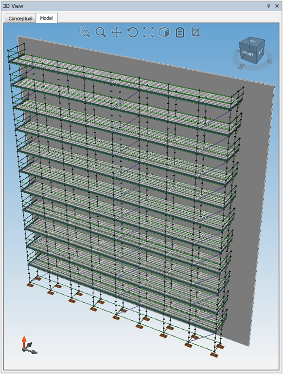
The scaffold appears to be 11 levels high.
The drawing shown here was created in Scaffold Designer®. It is an estimate based on what can be ascertained from the pictures of the scaffold failure and is sufficient for our leg load calculation.
During the creation of construction drawings, scaffolding engineers perform a simple leg-load check to make sure the scaffold legs can hold the weight. Although lots of other elements are also checked, this is the primary one. The design load (referred to as the “allowable leg load”) for a ring type of scaffolding like this one is around 5,000 lbs. per leg. Each leg is checked to make sure it doesn’t exceed this value. The allowable load has a 4:1 safety factor, which means the ultimate failure load is 20,000 lbs.
It is likely that the interior leg doesn’t have diagonal bracing, which further reduces the allowable leg load. Therefore, for this case, let’s consider a conservative decrease of 20% of the leg load.
Allowable Leg Load: 4,000 lbs.
Failure Leg Load: 16,000 lbs.
When calculating a simple leg load for a scaffold like this, we assume that it will have proper bracing, footing, ties to the building, etc. If not, we account for these in our calculations. If the final leg load is close or matches the allowable, and the contractor cannot reduce the size of the scaffolding, then further analysis is commonly performed using 3D structural analysis software.
There are two types of load to consider when calculating leg loads: dead load and live load.
The dead load is the weight of the scaffold itself as well as anything permanently attached to the scaffolding. Dead load does not change throughout the life of the scaffold. Live load is a variable loading that may change, such as people walking around or load from bricks or sand from blasting operations.
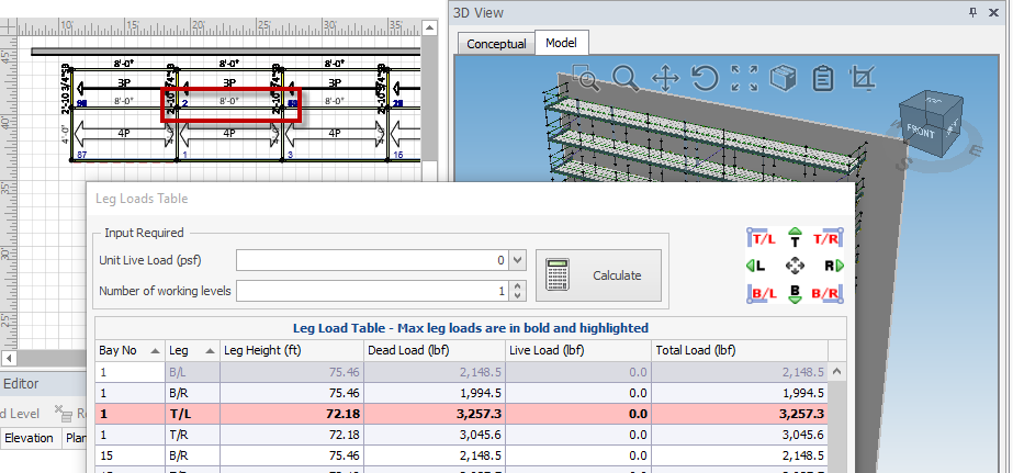
Using Scaffolding Designer we can see that the highest dead load (mostly from the steel planking) is 3,275.3 lbs. and it’s on the interior leg that is closest to the wall.
Dead Load: 3,275 lbs.
Live loads are standardized across the world and any engineer that designs scaffold knows what they are and when to use them. In the US, we use 25 psf loading for light duty, 50 psf for medium, and 75 for heavy duty. This is bricklaying, so it is 75 psf, but that includes the loading from the brick on the scaffolding. Because we’re going to use the actual weight of the brick, let us use the industry average for only people, which is 25 psf.
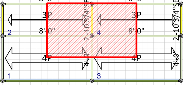
The leg load due to only the live load, on one bay, is 25 psf times the tributary area of the bay (shown below – 8 feet by 4 feet – 10.75 inches, which includes the side bracket).
| Tributary Area | 39.2 sf |
| Live Load | 25 psf |
| Working levels | 1 |
| Live Leg Load (lbs.) | 980 |
For our calculation we’re also going to add the actual load of the brick to see what happens. A pallet of bricks is around 2,500 lbs. and it appears about a half of a pallet was placed on each bay, or 1,250 lbs.
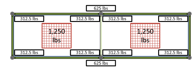
This 1,250 lbs. is divided by 4 legs resulting in 312.5 lbs. per leg. However, in bays that share a leg, both shared legs receive the weight of this tributary load. Each shared leg now bears 625 lbs. per level. Amazingly, it appears that all of the levels are loaded with brick. This is 625 lbs. per leg per level times 11 levels, which results in a total brick weight on the scaffold of 6,875 lbs. per leg.
Since we now have our dead load, live load from people, and brick loading, we can calculate the total leg load.
| Dead Load | 3,275 |
| Live Load | 980 |
| Brick Load | 6,875 |
| Total Load (lbs) | 11,130 |
The total load of 11,120 lbs is only one pallet of bricks away from an ultimate failure load. However, the leg load when only considering dead and live loads (4,255 lbs.) and not including the brick load still exceeds the allowable of 4,000 lbs, which is very bad.
Remember that, like all science, we make a lot of assumptions here to decide why it ultimately failed. We don’t know the exact configuration or loading of the bay that failed first, nor if there was any other loading. There is an unconfirmed report of a car hitting the scaffolding, which could be a contributor, but unfortunately the scaffold is still overloaded and could have survived a car destroying a leg. At no point in time should a scaffold ever violate a 4:1 safety factor.
As with any failure, it is often not one thing that is solely at fault. Even the Titanic sinking falls into this category. Although the major cause was a collision with an iceberg, the ship itself was declared “unsinkable” because it had double steel hulls. In the Titanic’s case it turns out that the carbon used to manufacture steel at the time had a high concentration of sulfur, which made the steel extremely brittle at cold temperatures. The hull effectively shattered like glass.
What could have been done to avoid overloading this scaffold in Houston? The biggest load is clearly from the bricks but the dead load is pretty high itself. The scaffold could have been built with a single level that could be moved as the bricks go up. This would also guarantee that no more than that one level would be loaded.
By: Brian Webb
There’s a quiet trend happening in scaffold design software, and if you’re a scaffold contractor, it’s worth paying attention to.… Read More

The NASC Skills Gap Report 2026 has put a number on something every scaffold business owner in the UK already… Read More

When speed becomes a service-level promise, not just an internal goal, it changes how clients choose you. Here’s what it… Read More
